Feeds:
Posts
Comments

Archive for the ‘Platform AutoCAD’ Category

Hi Everybody! Just to let you know, we have a great new website and blog for all to enjoy.

The website is amazing, containing information about training, services,  products, support and the latest news about upcoming events and blog posts.  You can even submit a support request online!

The new website is located at http://www.seiler-ds.com

new website


Also, our blog has moved to http://www.seiler-ds.com/blog

We will have a “Sign Me Up” button soon, so you don’t miss a single post!

new blog location

Thank you for following, and have a great day!!!

Julia


Read Full Post »

If after installing a network version of Vehicle Tracking, you receive licensing errors when clicking on a function in the Vehicle Tracking ribbon, you may need to move a file to correct the installation.  Unfortunately, The Vehicle Tracking installer, when deploying a network version, creates a file in the wrong location.

Please click on the link below to access the information for the workaround needed to correctly configure Vehicle Tracking.

Autodesk says to please follow the instructions listed in the link below, but instead of moving the file, copy it instead into the new location.

http://knowledge.autodesk.com/support/autocad/troubleshooting/caas/sfdcarticles/sfdcarticles/Autodesk-Vehicle-Tracking-Failed-to-retrieve-a-licence.html

Any questions, please reply to this blog, or contact me at jcornelius@seilerinst.com.


Read Full Post »

When using Map 3D 2015, or Map 3D commands within Civil 3D 2015, some dialog boxes are not displayed, despite the fact that FILEDIA AND CMDDIA are set to 1.

This causes their message to be displayed on the command line instead of inside a dialog box.  This is caused by missing Map 3D support folders in the file search path.

To work around this issue, make sure the path to the ade.dcl file is set in the Support File Search Path.

To accomplish this, please follow these steps.

  1. On the command line type OPTIONS.
  2. Go to the Files tab and expand the section Support File Search Path
  3. Add the path : C:\program files\autodesk\autocad 2015\map\support\en-us
  4. Apply, and close the OPTIONS dialog box
  5. You must close and restart Map 3D or Civil 3D for these changes to take affect.

After adding this path to the support file search path, the dialog boxes should work as expected.

Any questions, please reply to this blog, or contact me at jcornelius@seilerinst.com.

Read Full Post »

If you are installing a new version of Autodesk software on a network, you must download and install the latest version of the Network License Manager to successfully activate your software.

To download the latest version, please click on the link below, which will direct you to Autodesk’s download page.

http://knowledge.autodesk.com/support/autocad/troubleshooting/caas/sfdcarticles/sfdcarticles/Latest-version-of-the-Autodesk-Network-License-Manager.html

Click on the link that matches your operating system and network type of your server, which will start your download.

Please see the list below for the LMTools versions required for network activation for the corresponding version of AutoCAD or other Autodesk products with the same version.

  • AutoCAD 2015 – Version 11.12
  • AutoCAD 2014 – Version 11.11
  • AutoCAD 2013 – Version 11.10.0.3
  • AutoCAD 2012 – Version 11.9.0.0
  • AutoCAD 2011 – Version 11.7.0.0
  • AutoCAD 2010 – Version 11.5
  • AutoCAD 2009 – Version 11.4.100.0
  • AutoCAD 2008 – Version 11.4.0.0
  • AutoCAD 2007 – Version 10.8.0
  • AutoCAD 2006 – Version 10.1.5
  • AutoCAD 2005 – Version 9.2.2
  • AutoCAD 2004 – Version 8.3a
  • ·AutoCAD 2002 – Version 7.1f

Any questions, please reply to this blog, or contact me at jcornelius@seilerinst.com.

Read Full Post »

If you are like most designers or engineers, you have probably worked on projects where cut and fill volumes were required on each cross section, and you were the lucky one chosen who had to sit and calculate all the volumes by hand. The problem is, when you finally finished doing the calculations, you found out the 3D model had changed, and it all needed to be redone, starting over again from the very beginning.  Unfortunately, this usually happened multiple times over the length of the project.  Not only did you have to recalculate the volumes, but you also had to update the volume callouts to match the new numbers.

If this has happened to you, and you are looking for a better solution, I can show you, in just a few easy steps, a way to have Civil 3D calculate the volumes, and insert a table on each section that shows the cut and fill volumes, which will then dynamically update whenever the 3D model is changed.

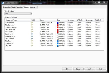
To accomplish this, the first thing that you want to do, is create a section view table, based on how you would like the volumes to show on your cross sections.  This is done by opening the section view module under the settings tab on the toolspace.  Open the node next to table styles, right click on total volume, and choose new.  This will open a dialogue box, allowing you to custom create the table you would like to use for your sections.  Under the information tab, give your style a name and description if you like.  Change the tab to data properties.  Here is where you can pick your text settings, sizes and which volumes you would like to use.  Lastly, go to the display tab, and choose the layers for your new table.  Click on apply and ok, and you are ready to go!

table style  basic data


table style basic display


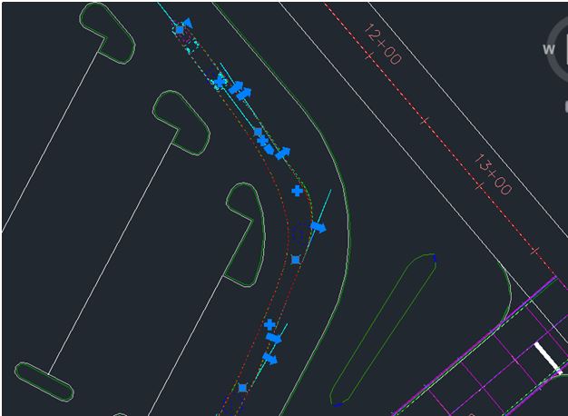
Once your section view table is complete, you may choose the compute material button 1 of 2 different ways, either by clicking on a section view and choose compute material in the launch pad in the ribbon, or switching to the analyze tab, and choose compute material in the volumes and materials panel.  This will bring up a dialogue box that allows you to pick an alignment and sample line group from the drawing.

compute materials 

select sample line group


Once you choose your settings, click ok, and the compute materials list dialogue box opens.  Next, pick your quantity takeoff criteria from the list, and the volume calculation method that you would like to use.  Set the existing and proposed surfaces you would like in the section below.  Once you have the settings completed, it is time for the next step.

edit material list

You are now ready to create your cross sections.  When you choose create multiple section views, you will notice that section view tables is no longer grayed out.  This is because we have already computed the materials list. When you get to this section, please choose total volume for the type of table, and your custom table for the style.  Click the add button on the right.  This area also lets you choose the position where you would like the table to be located based on the section view.

volume table basic

Click on create section views, and they will now have tables attached.

section with basic table


Below is another example of a volume table customized for your standards.

section with table

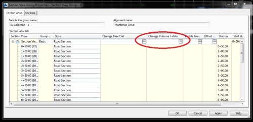
Don’t worry if you forget to add the table when creating the views.  It is easy to add them later if needed.  To accomplish this, highlight an existing section view.   In the ribbon, click on view group properties, and under the section view tab, click on the change volume table ellipse (the small button that looks like a dice).  Choose the table to add to the sections and hit ok. This will also allow you to change the location of the table on existing sections, if needed.

section view group properties

Just by accomplishing these few simple tasks, you will have cut and fill volumes located on each of your cross sections, that will dynamically update if the 3D model changes, and give you more time to devote to other projects.

Any questions, please reply to this blog, or contact me at jcornelius@seilerinst.com.

Read Full Post »

For those of you that use Pipe Networks in Civil 3D, sometime over the course of your career, you have probably needed to label a slope on a pipe based from the invert elevations at the inside face of your structures, instead of from the center (which is the default in Civil 3D), and have absolutely no clue how to go about creating a label style that will do just that.

Luckily, there is an easy way to accomplish this feat.

Most label styles in Civil 3D give you an option to use an expression in the layout of the label.  An expression is simply a piece of programming code that can be evaluated and yields a result, based on the information it is given.  Once we create an expression, Civil 3D will calculate the slope based on the length of the pipe, from the inside face of the structures, using the starting and ending inverts, thus calculating the true slope of the pipe.

To show you how it is done, let’s create an expression and a new label style.

Click on the settings tab on the toolspace.  Scroll down and expand the Pipe node, the label style node and finally the Plan Profile node.

pipe module

Right click on Expressions and choose new.  When the expression dialogue box opens, type in a name for the expression, and a description if you like.  Once you have named your expression, it is now time to create it.

expression dialogue box button

By clicking the first button on the right of the function keys, a list of programming codes that you may pick from for the creation of the expression will open.

expression list

We will choose the functions needed from this list.

The expression needed for our pipe label will be created beginning with the starting invert elevation, then subtracting the ending invert elevation and then dividing the difference by the 2D length to the inside edges.  Make sure to include the braces around the Invert elevation functions.

completed expression

Change the Format result from Double to Percent, since the desired result needed is the slope..  Click OK.

Now, if you click on expressions in the toolspace, you will notice in your preview area, that the new expression is now listed.  This shows that the expression was created.

expression listed

Since we now have the expression created, the next step will be creating our label for our pipes.  Right click on Plan Profile, under label styles, and select new.  Under the information tab, give your new label a name and a description if you would like.  Under the layout tab, click on the value tab of the text contents.

label layout tab

Once the text component editor opens, choose your expression in the list on the left.  It should be listed at the top on the left.  Set your precision to the value that you want, and then click on the arrow pointing to the right to update your contents.  Click OK.

text component editor

Your label is now ready to use, and will correctly label your pipe slopes from the inside of the structures, instead of center to center.

Just by taking a few minutes to create an expression and a new pipe label, you can save time by not having to hand calculate all the slopes.   Your pipes will now be labeled correctly, and will automatically update if the network changes.

Any questions, please reply to this blog, or contact me at jcornelius@seilerinst.com.

Read Full Post »

Autodesk Vehicle Tracking is software that Autodesk has added to its lineup for 2014. The software runs within the host application which includes   AutoCAD, AutoCAD Civil 3D, AutoCAD Map 3D, AutoCAD Architecture, AutoCAD Plant 3D, and AutoCAD Utility Design.

This new software is a design solution for integrated swept path analysis and is a comprehensive transportation review software. The dynamics of the software allows engineers, designers, and planners to accurately evaluate vehicle movements on site design projects. Besides being used for vehicle swept path analysis, it also has creation tools for parking stalls and roundabouts.  Here are some screen shots of what the user interface looks like.

Vehicle Tracking Bar

Ribbon

Vehicle Tracking Cars Popup

Vehicle Standards Explorer

The following screen shots depict a vehicle swept path, 3D of that swept path, parking bay creation with report, and a roundabout. It is important to note that all entities have grips that allow for easy manipulation.

Vehicle Path

Vehicle Swept Path

vehicle tracking 3d truck

3D Animation Swept Path

Parking with report

Parking Bay with Report

Roundabout 3

Roundabout

I will be doing videos of each of these functions in future posts.

If you have any questions or would like to schedule a demo, please reply to this blog, or contact Rodney Holland at (rholland@seilerinst.com)

Read Full Post »

Autodesk YouTube Channel –  An important website for Autodesk users is the Autodesk YouTube channel. With over 73,000 subscribers and approx. 25 million video views, it has a tremendous amount of information and value.

Read Full Post »

autodesk

If you’ve not seen it, Autodesk has a page dedicated to their mobile applications:

http://usa.autodesk.com/adsk/servlet/pc/index?siteID=123112&id=16953811

There are some great Apps there. Some I’d recommend exploring include  Autodesk BIM 360 Glue Mobile App,  Autodesk FormIt,  Autodesk SketchBook Mobile, and AutoCAD WS.

Read Full Post »

I am currently on-site participating in a Seiler training and I just realized that I’ve never discussed our training here.  We are an Autodesk dealer and have active training centers.  To begin, start by checking out our Public training options:

http://tinyurl.com/seilert

These are just a small percentage of the trainings that we offer. Traditionally, our most popular trainings have been custom trainings where we come to your location and provide trainings of multiple lengths and focus areas for your staff.  While we can do “by the book” trainings, our favorite trainings go outside the book and focus on your needs and questions.  Why? Because your needs and requirements make you unique and give you an edge on your competition. So if you are curious on how we can aid you in achieving your personal, professional and organizational goals, give us a call!


Read Full Post »

Older Posts »