Feeds:
Posts
Comments

Archive for the ‘Revit MEP’ Category

Hi Everybody! Just to let you know, we have a great new website and blog for all to enjoy.

The website is amazing, containing information about training, services,  products, support and the latest news about upcoming events and blog posts.  You can even submit a support request online!

The new website is located at http://www.seiler-ds.com

new website


Also, our blog has moved to http://www.seiler-ds.com/blog

We will have a “Sign Me Up” button soon, so you don’t miss a single post!

new blog location

Thank you for following, and have a great day!!!

Julia


Read Full Post »

How can I make Revit Schedules look the way I’d like them to look?  I hear this question a lot.  In Revit 2014 there are a couple new options. You’ve been able to change the font in past versions, but now you can now add an image in a schedule, and shading of columns is also possible.  I’ve listed a couple How To’s for you to try.

To shade a column in a schedule:

  1. Open your schedule for editing, select the column header, and a new panel on the toolbar will appear.new panel
  2. Select shading and the color, and that color will be added to the column.shading columns

*this would be ideal for schedule with a lot of columns making it easier to read.

Another Option is adding an image to your schedule. 

  1. Open your schedule and go to properties.  Select Edit Fields in your Properties and another window will open up.
    properties
  2. In this window under Available Fields select the Image parameter and Add it to Scheduled Fields. Select OK.

    schedule fields
  3. Now the Image column has been added to your schedule.  schedule
  4. Select in the Image Field and you will see a little box.  Select the box to add your image.
  5. Another window will pop up.  Select Add, choose your image and select OK. Select OK again to add it to schedule.add image
  6. In the schedule you can see the image name that you just added but you cannot see the image until you put it on a sheet.table
  7. Create a new sheet and drag schedule onto the sheet.  You will now be able to see the image in the schedule.finish

Read Full Post »

Are you looking for a way to automate scheduling to reduce errors?   Key Schedules are a good way to do that.   Schedules can contain multiple items with same characteristics. For example, a room schedule might have 50 rooms with the same floor, ceiling, and base finishes. Instead of having the tedius task of entering all this information manually for all 50 rooms in the schedule, you can create a key that automatically fills in information.

Speed up your process by using Key Schedules in current schedules:

1.            Open my Room Schedule and decide what information will be used.

room schedule

2.            Next go to View, Create Panel, select Schedules.  Under Category select the type of schedule (I selected rooms f or the Room Schedule), Name your schedule, select Schedule Keys, and name the Key schedule, then select OK.

key schedule

3.            Schedule Properties Window will pop up.  Under “Available fields” select the fields you want to add to the key schedule and select add. After all fields have been added, select ok.

  • Hint:  keep a view of the Room Schedule so you can add the fields in the same order as what is on the Room Schedule


 finish properties


4.            The Room Finish Schedule will be generated and that view will be shown.  Now you will need to add your finish types.  On the toolbar on the Rows panel, select Insert, Data Row.  A row will be added, and a Key Name 1 will appear. Repeat this step as many times as you need for the finishes. Then fill out the finishes.

 finishes

ROOM FINISH SCHEDULE

 5.            Next you will need to add the Key schedule into the Room Schedule.  Open the Room Schedule, go to Properties, and select Fields.  On the left under “Available Fields” select Room Finish (or the name of your Key Schedule) and ADD it to the Schedule Fields.  Select OK.

 schedule add key


6.            The field Room Finish has now been added to your schedule.

room sched. add.

7.            As you select the number of finish you would like, the key schedule will populate the schedule.

6. add key sched in room schedule


7.


 Any questions, please reply to this blog, or contact me at pbeard@seilerinst.com.


Read Full Post »

One common approach during Preliminary Design is Design Options, especially in Architectural firms.  Project owners and designers will want to see some alternatives.

How the building will look in plan, section, and 3D view?

What if we move this wall over here?

What if we split this space into two separate spaces?

So how we do that in Revit?

Do we have to have a separate model for that?

No we don’t!   Revit provides tools for developing design options within a single model.  Its functionality allows you to create views that show each option so the designs can be compared.  Once you settle on a design it can be set as the primary and added to the main model.  Doing this will delete the other options that you won’t use. Here is the basic process I follow using design options:

  1. First you must have a main model that includes all the elements you need plus all the elements that will not be affected by the options.   Elements in the main model are always visible by default.  (Optional:  You can create views to show each option separately and pull those views onto sheets.)
  2. Go to the Manage tab, Design Options Panel and select Design Options (also located at the bottom of your screen in the status toolbar).  In the Design Options Window select New in the Option Set area to create a new option set.  (it will automatically create one design option within the set) 1-design opt

3.  Select New in the Options area of the window to create another option.

4.  Start adding elements to one of the two options.  (everything in the  project is currently in the main model)

5.  Select the element you want to add to the new option.  While selected, go to Manage tab, Design Options panel and select the Add to Set button.  The  Add to Design Option Set window will appear.  Check mark the option in which you want the wall to be shown, uncheck the one you do not want it shown in. design option set ***when the item is added to another option is becomes un-selectable within the main model.

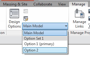
6.   Next you will want to add elements into each option, this is called Entering Edit Option Mode.  Easily done by going to the Manage tab,  Design Options panel and selecting the drop down list of Design Options.                    (notice that all elements in the other options no longer can be seen) design option drop down

  1. Now that you are in Option 2, add elements for that Option.  You can add, delete, and modify elements for option 2 in this mode.  To exit the mode go to Design Options drop down list and select Main Model.  (only the primary option will appear by default)


  1. Set up views.  Since you created views to show the different options, you now need to set the visibility of that view to show the appropriate option.  Go to Visibility Graphics (VG), Design Options tab, under Design Option select the drop down arrow and select the Option you would like to show in that view.  This will lock the view to show only the Option selected.  Then drag that view onto a sheet.

design option vg

  1. After all Options have been considered and one selected you may want to delete the other options out of the model.  To do this select Design Options (the dialog box will appear), select the option you want to make primary, then select Make Primary on the lower right under Option.  Next go to Option Set and select Accept Primary.

design option primary

10.  Another window will appear with warnings and confirmations before completing the process.  After deleting the options they will be permanently deleted from the model.  Make sure you no longer need them before completing this step. design option warning

Any questions, please reply to this blog, or contact me at pbeard@seilerinst.com.

Read Full Post »

Have you ever had an instance where you wanted a symbol to show in one view but the symbol and object to show in another view?  You could approach this a couple different ways: (1) you could adjust the visibility settings so that the object wouldn’t show in certain detail level like Fine, Medium ,Course.  (2) you could add a parameter in the family for control over when to show it and when to not show it.  Visibility settings wouldn’t work for me in this case because i wanted it to show in other plan views, so i added a Yes/No parameter in the Family.

Here are the steps I took to Add the Yes/No Parameter in a Revit Family:

  1. Open the family in Family Editor
  2. In the Project Browser go to Floor Plans and open Ref. Level.
  3. Select the area you want to control visiblity of.
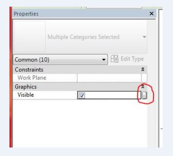
  4. Go To Properties, Under Graphics select the Associate Family Parameter Option Bar (A pop up window will appear) Image
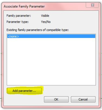
  5.  In the Associate Family Parameter window select “Add Parameter” located at the bottom left.  Image
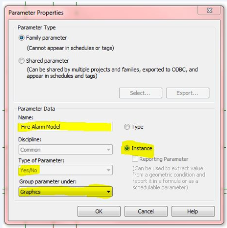
  6.  A new Parameter Properties window will open.
  • Name describing this option
  • Yes/No should already be selected as Type of Parameter
  • Group under Graphics (this is where it will be listed in properties for you to turn on/off),
  • Select Instance
  • Select ok

Image

7. Select OK.

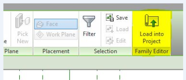
8. Load edited family back into Project.

Image

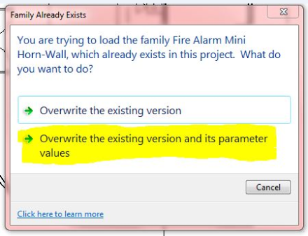
9.   If family already exists in project you will get this window.  Select Overwrite the existing version and its parameter values

Image

10.  Now Select the family in view and go to Properties to find the new parameter you created.  Check or Uncheck for that view.

 
Any questions, please reply to this blog, or contact me at pbeard@seilerinst.com.


Read Full Post »

If after installing a network version of Vehicle Tracking, you receive licensing errors when clicking on a function in the Vehicle Tracking ribbon, you may need to move a file to correct the installation.  Unfortunately, The Vehicle Tracking installer, when deploying a network version, creates a file in the wrong location.

Please click on the link below to access the information for the workaround needed to correctly configure Vehicle Tracking.

Autodesk says to please follow the instructions listed in the link below, but instead of moving the file, copy it instead into the new location.

http://knowledge.autodesk.com/support/autocad/troubleshooting/caas/sfdcarticles/sfdcarticles/Autodesk-Vehicle-Tracking-Failed-to-retrieve-a-licence.html

Any questions, please reply to this blog, or contact me at jcornelius@seilerinst.com.


Read Full Post »

When using Map 3D 2015, or Map 3D commands within Civil 3D 2015, some dialog boxes are not displayed, despite the fact that FILEDIA AND CMDDIA are set to 1.

This causes their message to be displayed on the command line instead of inside a dialog box.  This is caused by missing Map 3D support folders in the file search path.

To work around this issue, make sure the path to the ade.dcl file is set in the Support File Search Path.

To accomplish this, please follow these steps.

  1. On the command line type OPTIONS.
  2. Go to the Files tab and expand the section Support File Search Path
  3. Add the path : C:\program files\autodesk\autocad 2015\map\support\en-us
  4. Apply, and close the OPTIONS dialog box
  5. You must close and restart Map 3D or Civil 3D for these changes to take affect.

After adding this path to the support file search path, the dialog boxes should work as expected.

Any questions, please reply to this blog, or contact me at jcornelius@seilerinst.com.

Read Full Post »

If you are installing a new version of Autodesk software on a network, you must download and install the latest version of the Network License Manager to successfully activate your software.

To download the latest version, please click on the link below, which will direct you to Autodesk’s download page.

http://knowledge.autodesk.com/support/autocad/troubleshooting/caas/sfdcarticles/sfdcarticles/Latest-version-of-the-Autodesk-Network-License-Manager.html

Click on the link that matches your operating system and network type of your server, which will start your download.

Please see the list below for the LMTools versions required for network activation for the corresponding version of AutoCAD or other Autodesk products with the same version.

  • AutoCAD 2015 – Version 11.12
  • AutoCAD 2014 – Version 11.11
  • AutoCAD 2013 – Version 11.10.0.3
  • AutoCAD 2012 – Version 11.9.0.0
  • AutoCAD 2011 – Version 11.7.0.0
  • AutoCAD 2010 – Version 11.5
  • AutoCAD 2009 – Version 11.4.100.0
  • AutoCAD 2008 – Version 11.4.0.0
  • AutoCAD 2007 – Version 10.8.0
  • AutoCAD 2006 – Version 10.1.5
  • AutoCAD 2005 – Version 9.2.2
  • AutoCAD 2004 – Version 8.3a
  • ·AutoCAD 2002 – Version 7.1f

Any questions, please reply to this blog, or contact me at jcornelius@seilerinst.com.

Read Full Post »

Leveraging point cloud data can be an effective tool in creating an accurate model of a difficult space.  Take this room for instance:

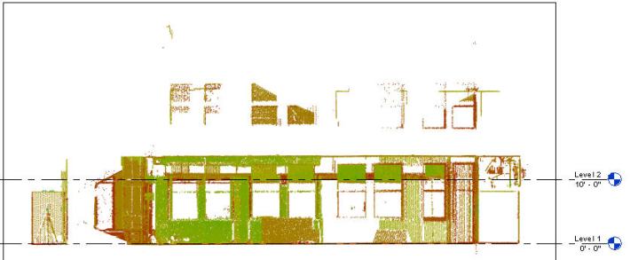
Image

Image

This space has crumbing walls, no ceiling, collapsing duct, and creates a condition where individuals can’t visualize what the space could look like.  How do we communicate what this space COULD look like?

For us we started with a quick point cloud scan then brought it into Revit:

Image

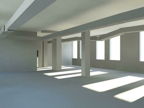
From this scan we were able to model the room’s current dimensions accurately (as well as the falling duct) in order to produce a conceptual illustration of what this room could look like as a blank slate.

Image

From there we could have modeled it more, but it worked for our purposes. I did this rendering with the duct “falling down” as a visual que that yes, this is the same space, but that we could replace the duct and easily “clean it up”.

The entire time to complete:  For two people, one working on the scan and one working in Revit, we could have started the scan at 9:00 AM and been to a point where the “white” model was done by 3:30 in the afternoon… including lunch and the 30 minute drive back to the office from the site.

If you would like to know more, let us know ( you can email me, Brian Myers, at bmyers@seilerinst.com ) and we’ll be happy to discuss.

Read Full Post »
I was recently asked:  “I have a CAD background that has been scanned in as an image file. I want to see it on every floor when I’m drawing and I don’t want to move it on accident… can I do it? ”

While technically we can insert an image in, we sometimes forget about two functions: Paste Aligned and Groups.

Paste Aligned allows you to copy the image directly up without the need of worry if each image is inserted in the exact same spot.  It will be.  It can be found under the Modify tab on the ribbon.

Using the same logic, you could also include the image in a Group. By placing it in a group, you could then update the image on one floor (perhaps adding multiple images, CAD files, etc) and have it auto-populate the change on every floor.

To address the other issue (moving by accident) it just takes a Pin of the image / group and it won’t move.

In short, if all you have is an image file and you need to use it on multiple floors, remember that copy – paste aligned under the manage tab could be a useful tool for the process.

Read Full Post »

Older Posts »