Recently, a surveyor asked me if Civil 3D could automate the insertion of staking points along a finished corridor. At first glance, I thought Civil 3D could do the entire job in just a few clicks. Simply select the corridor, and then expand the Launch Pad ribbon panel to access the “Points from Corridor” tool. Using this tool you can easily place COGO points along any of the feature lines in the corridor.
It turns out; this isn’t exactly what the gentleman wanted. He was interested in placing COGO points along feature lines at a specified offset. To do this, (while not difficult) requires a little more effort.
Let’s take a look…
I’m starting with a simple corridor…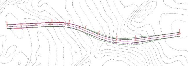
Below is the assembly this corridor is based on…
The assembly is built from the BasicLane and BasicCurbAndGutter subassemblies and includes a DaylightMaxWidth to tie back to the existing surface. Now, let’s say I’d like to stake the back of curb feature line at a 3’ offset. To do that, I’ll make a change to the assembly.
(At the risk of “destroying the end of the movie” here, I am simply going to create some NEW feature lines at a 3’ offset from the back of curb.)
Step 1: Use the SAVEAS command and save the corridor drawing as a “working drawing”. Then Press CTRL+3 to access the Tool Palette and set the Generic tab current.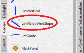
Step 2: Select the “LinkWidthAndSlope” subassembly and click to place one on the left (and right) back of curb. Press ESC when finished.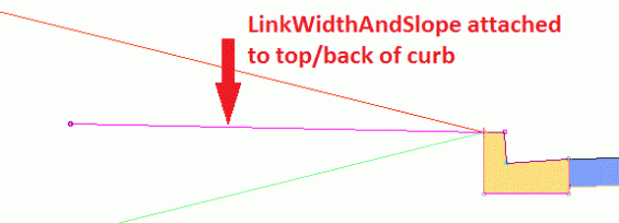
Step 3: Select both LinkWidthAndSlopes, and in the Properties Palette, make the following changes.
Width = 3’ – (Offset distance)
Slope = 0.00% – (Flat slope, same elevation as top back of curb)
Point Codes = 3’O/S CG – (Eventual name of feature line and COGO point description)
Omit Link = Yes – (No need for link to display)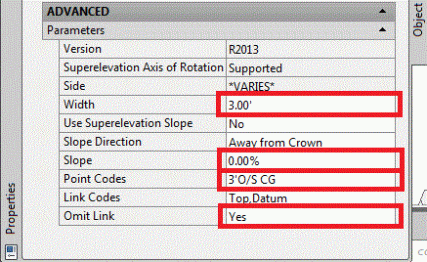
When finished, select the corridor and in the Modify Corridor ribbon panel, click “Rebuild Corridor”. At this point you will see the additional 3’ offset feature lines displaying in the plan view…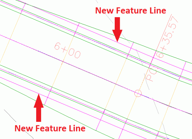
Step 4: Change the corridor assembly frequency settings. We do this because the automated point tool will create points at EVERY assembly insertion. By adjusting the frequency, we can control how often points are inserted. Select the corridor, right-click and choose “Corridor Properties”. On the Parameters Tab, click the “Set All Frequencies” button and in the pop-up dialog box, assign the following values…
Along Tangents = 50
Along Curves = 50
Along Profile Curves = 50
This will place COGO points at every 50 feet along the alignment stationing. Note that (based on the other settings) COGO points will also be placed at PC’s, PT’s, High/Low Points, etc.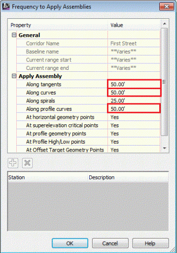
When finished, click OK to close both dialog boxes, and rebuild the corridor.
Step 6: Create COGO Points. Select the corridor and then expand the Launch Pad ribbon panel and choose “Points from Corridor”. In the Create COGO Points dialog box, make the following adjustments…
Select the “For entire corridor range” radio button – (This will apply points to the full length of the corridor)
New point group name: = 3’ offsets CG – (Name for new point group)
Point codes to create: = 3’O/S CG – (Code to assign points to)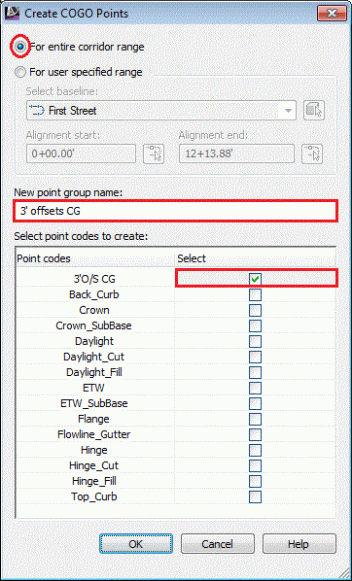
Click OK to insert COGO points to drawing.
After zooming in, you’ll find that you have new COGO points, having the elevation of the top back of curb, and inserted at 3’ offsets.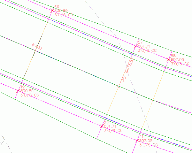
Try experimenting further with this method of point creation. As an example, try visiting the Construction Tab of the Assembly Properties. In there you can match the slope of the LinkWidthAndSlope to another slope in the assembly (the lane slope perhaps?). This would be a great way to stake edge of pavement offsets whose elevation matches the slope of the lane.
Something else I was asked recently 🙂
Using the LinkWidthAndSlope subassembly can be an effective way to create COGO points for much of your corridor staking needs.